Electrified Mortise Lock Specification Guide for Access Control
An electrified mortise lock specification guide covering power, fail-safe behavior, door compatibility, access-control integration, wiring, commissioning, and maintenance.
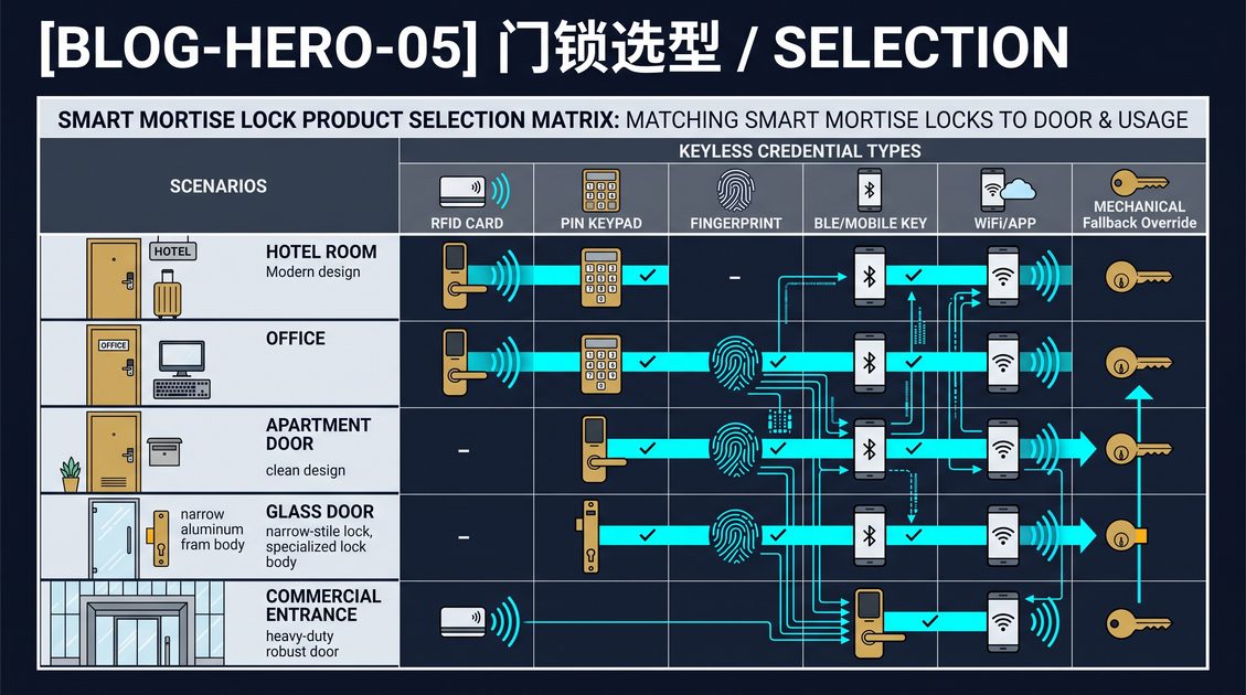
An electrified mortise lock is a mortise lock body that releases or secures its latch and bolt through an electrical signal from a reader, controller, access panel, or building-management system. Unlike a battery-only smart lock, it is normally part of a wired access-control architecture, so its specification must cover the mechanical case, power input, release behavior, wiring route, controller interface, and emergency operation. This electrified mortise lock specification guide explains the information a buyer or integrator should request before selecting hardware, without assuming that one voltage, current, or fail mode applies to every model.
Electrified Mortise Lock Specification Guide: Mechanical Fit
Start with the door and frame. Confirm the case height, width, depth, backset, faceplate, latch and bolt arrangement, handle height, handing, and strike geometry. The pocket must accept the complete body and the strike must align when the door closes. A motorized or solenoid-driven lock cannot reliably correct a warped door, a tight seal, or an offset strike.
Record whether the opening is a new build or retrofit, whether it is rated, and whether a closer, panic device, glass panel, or metal construction changes the installation. The exact body drawing matters more than a product-family label. Request the manufacturer’s current mechanical and electrical documentation for the selected variant.
Electrified Mortise Lock Specification Guide: Power and Release Mode
The electrical specification should state input range, normal and peak current, connector type, cable requirements, and behavior during power loss. Do not infer these values from another lock or controller. A system may be fail-safe, releasing on power loss, or fail-secure, remaining locked from the outside when power is removed; the correct behavior depends on the opening, life-safety rules, and the authority having jurisdiction.
Define how the inside release works and whether emergency egress remains mechanical and immediate. Power supplies should be protected, sized for startup demand, and tested under normal and interrupted conditions. Battery backup may be required for continuity, but it does not replace a compliant emergency-release design.
Electrified Mortise Lock Specification Guide: Integration
An electrified mortise lock may receive a signal from a keypad, RFID reader, biometric reader, mobile-access controller, or central access panel. Specify the interface and logic: which device authorizes release, how long the release lasts, how door position is sensed, and where events are recorded. For networked systems, document what remains functional if the controller or network is unavailable.
Wiring needs a protected route through the door, strain relief, and clear service access. Keep conductors away from moving bolts and spindles, and label both ends. A commissioning record should include the lock identifier, controller port, power source, release mode, administrator, and emergency procedure.
Electrified Mortise Lock Specification Guide: Testing and Service
Test the complete opening with valid and invalid credentials, power interruption, controller failure, network loss, door position, inside egress, manual override, and repeated cycles. Confirm that the door closes without excessive force and that the latch and bolt fully engage. Test representative doors when a project uses several hardware batches.
Maintenance includes inspecting alignment, strike, fasteners, cables, seals, controller logs, permissions, and backup power. This electrified mortise lock specification guide is general information; obtain qualified review for fire, accessibility, electrical, privacy, building, and emergency-egress requirements before procurement.
Electrified Mortise Lock Specification Guide: Wiring Documentation
A useful specification records the complete circuit rather than only the lock name. Identify the power source, protective device, cable route, connector, controller output, request-to-exit input, door-position input, and any backup supply. Mark both ends of each conductor and preserve the wiring diagram with the door record. This makes troubleshooting safer and prevents a later installer from guessing which circuit controls release.
Commissioners should verify the voltage and current at the lock under normal operation and during the actuator’s start event, using equipment and procedures appropriate for the installation. Do not substitute an unverified power supply because an apparently similar output can create unreliable release or damage. The final record should state which values were measured and which were supplied by the manufacturer.
Electrified Mortise Lock Specification Guide: Operating Policy
The lock’s electrical behavior must match the building’s operating policy. Decide whether the door should remain secure during a communications outage, a local power interruption, or a fire-alarm event, and coordinate that decision with the responsible safety professionals. Define who can issue release commands, how long a release lasts, and how the inside user exits without a credential. Document the manual recovery method and test it with the system in each relevant state.
For a multi-door deployment, use a pilot opening to validate the controller, door closer, cable route, and monitoring events before repeating the installation. A clear specification connects electrical behavior to the people and procedures that operate the building.
Not sure which sensor fits your project?
Talk to our mmWave application engineers for a free consultation.
Specify your hotel project with our engineers
Send your room count, ceiling type, and protocol preference. We will return a sample plan and quote within 24 business hours.
- Move from general guidance into a product or application discussion.
- Use RFQ when pricing, drawings, MOQ, or launch timing needs structure.
- Keep a direct contact path visible for fast clarifications and handoff.